Innovation and technological evolution offer new advantages and benefits, not only at the operational level, but also in terms of their reduced impact on the environment.

Innovation

New concept of power backup for telecommunication networks!

Battery-FREE Power Supply and Backup Solution for HFC networks is a Patented and Innovative Technology that provides an Integral Solution to the Problem of Power Provisioning, Assurance and Backup for HFC networks, without Batteries or External Generators.

Innovative Criteria:

  • Provision of power backup schemes among nearby power sources.
  • Provision of backup power supply for unlimited time.
  • Lower-cost support of multiple power failure scenarios.
  • Increased efficiency of grid power use.
  • Optimization and focus on maintenance tasks.
  • Broadening of power supply's power coverage area.
  • Offer of a green, environmentally friendly solution.
User-friendly and easy-to-install technology requiring simple maintenance

The EPS is much smaller in size than the UPS Power Supplies... Read more

Tecnología amigable, de fácil instalación y mantenimiento sencillo
OPEX and CAPEX costs optimization

The major savings occur during the operational phase, which involves clearly tangible costs, such as the mandatory... Read more

Tecnología Verde
Green Technology

The solution is conceived on the basis of obtaining the maximum possible electrical efficiency by using suitable... Read more

Opción monitoreo local y remoto
main image
Mejoramiento de costos
Local and remote monitoring option

It is a solution's local and remote communication interface that enables local information to be provided... Read more

Provisión de energía desde distintas fuentes
Immediate response to a power outage for an indefinite period of time

In practice, the solution works as 2 independent networks... Read more

Respuesta inmediata a cortes de suministro eléctrico por tiempo indefinido
Power supply from different power sources

Together with the backup between the 2 circuits that takes place between the 2 IPSUs... Read more

imagen
Advantages of Sinusoidal Vs Ferroresonant PS

Summary of technical/economic benefits of the Secure Power Full solution... Read more

imagen

The EPS Power Supply (ECO Power Supply)is much smaller in size than the UPS Power Supplies, and it is not necessary to handle heavy batteries and other devices of the solution. The IPSU and IVA, which are no larger than a small line amplifier and very lightweight are designed to be easy to handle and connect, as well as easy to maintain, thus providing the possibility of visual communication among the devices and the technician by means of LEDs, small voltmeters and ammeters, together also with the possibility of downloading the information to the installer's cell phone via Bluetooth technology.

The devices have simple and modular elements, and make the Secure Power Full solution an innovative and user-friendly solution for network designers, installers, monitoring (NOC), and maintenance crews in other words, an ideal ally to achieve the maximum performance of human and material resources of the companies that rely on the SECURE POWER FULL solution.

Capex

The Secure Power Full solution consists of only 3 key elements (for the purpose of economic comparison), the IPSU intelligent switch, the IVA power amplifier and the EPS sinusoidal power supply, therefore this at a lower cost by approximately 10%.

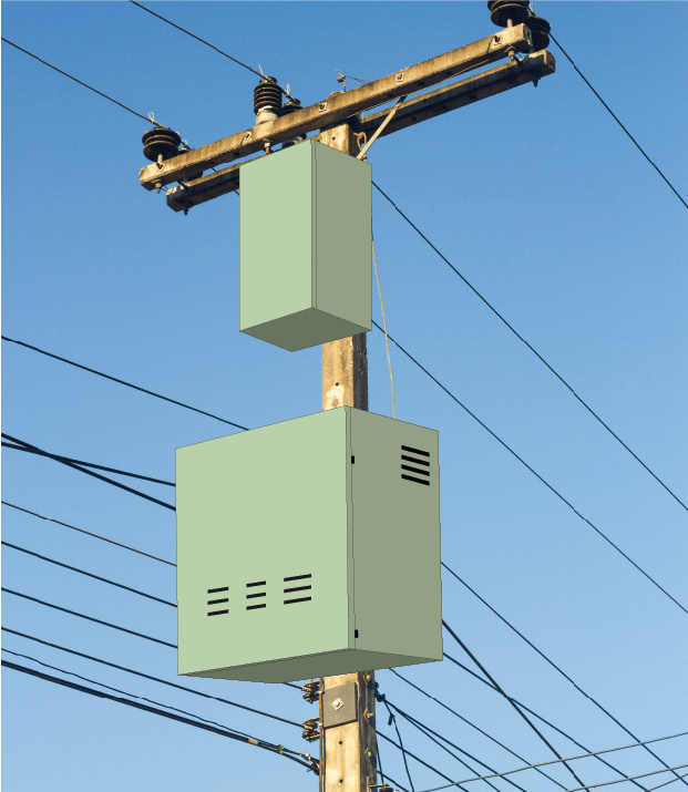
The traditional solutions for network energization and continuity of operation in case of power failures, which are based on UPS with batteries, have a set of components that include, among other elements, a ferroresonant source, a direct current (DC) inverter module from batteries to alternating current (AC), a large cabinet to place the aforementioned elements.

OPEX benefits & savings

Once the SECURE POWER FULL solution is installed, there are considerable savings in terms of “Fixed Costs” associated with the maintenance of network energization.

Below you will find some points to take into account when analyzing the advantages of our proposal.

Replacement cost – for large operators it is estimated that 25% of the equipment will be replaced starting with the first cycle and in the following years, until the end of life.

The major savings occur during the operational phase, which involves clearly tangible costs, such as the mandatory annual battery replacement, which is easy for us to measure, in addition to the operating costs of battery collection, preventive maintenance, storage and/or destruction of batteries, support crews, generators, administrative personnel to deal with complaints, administrative and warehouse personnel for the purchase of batteries, subscribers’ poor perception of "good service", all of which is very difficult to calculate since there are discrepancies depending on the company and the country.

5-year projected cost analysis:

As shown in the graph below, OPEX is significantly reduced for the SECURE POWER FULL solution, with OPEX being close to zero.

Investment Yearly

NOTE: Based on information provided by an operator with 9,000 UPS Power Supplies, with 3 batteries each, which represents a quantity of 27,000 batteries, the annual replacement is 25% of the total batteries (equivalent to 6,750 batteries). This shows that, in addition to the savings on the initial investment, the use of an innovative battery-free power backup solution allows the operator to make its OPEX tend to zero.

Benefits

  • It allows the operator to offer new services that demand high reliability, thus generating new revenues.
  • It improves customer service quality, customer experience and customer satisfaction.
  • The use of a “Green” (non-polluting) solution demonstrates the operator’s interest in protecting the environment in general and the local community it serves, in particular (CSR). (Socially Responsible Companies).
  • Maintenance operations are minimized.
  • The use of generators is significantly reduced.
  • The number of user complaints about power outages is reduced.
  • Service availability and network reliability are increased.
  • Avoidance of the use of special fittings (theft prevention).
  • Efficient use of grid energy – reduction of electricity supply bills.
  • RReallocation of obtained savings to other relevant areas.

The EPS Power Supply (ECO Power Supply) is much smaller in size than the UPS Power Supplies, and it is not necessary to handle heavy batteries and other devices of the solution. The IPSU and IVA, which are no larger than a small line amplifier and very lightweight are designed to be easy to handle and connect, as well as easy to maintain, thus providing the possibility of visual communication among the devices and the technician by means of LEDs, small voltmeters and ammeters, together also with the possibility of downloading the information to the installer's cell phone via Bluetooth technology.

The devices have simple and modular elements, and make the Secure Power Full solution an innovative and user-friendly solution for network designers, installers, monitoring (NOC), and maintenance crews in other words, an ideal ally to achieve the maximum performance of human and material resources of the companies that rely on the SECURE POWER FULL solution.

The solution is conceived on the basis of obtaining the maximum possible electrical efficiency by using suitable technologies and avoiding the use of batteries, which, by their very nature, are highly polluting.

Effectiveness Graphic
imagen

It is a local and remote communication interface that allows to give information about the status of the local solution to the technician working on site, showing the measurements of currents and working voltages or operation of inputs and outputs of EPS, IPSU, IVA, ISPA, as well as alerts when the surge suppressor reaches 50% of its capacity and if the EPS source is energized by the main input or the auxiliary voltage input.

These operating parameters can be checked by the technician on site via a Bluetooth interface on his mobile device.

In turn, it sends this information through the DOCSIS IP platform to the Control Center, (NOC) which can manage tens, hundreds or thousands of these devices simultaneously, take corrective measures in case of power supply disruptions, as well as provide accurate failure rates and be able to foresee the necessary corrective actions.

imagen

  • It can import complete Tree View in CSV files. (values separated by commas)
  • It can detect one node at a time from the User Interface (on -demand discovery).
  • Network Detection
  • It can export Tree View for later use.
  • Detection can be backed up.
  • Complete automated EPS/IPSU/ISPA/IVA back up topology.
  • Autodetection of PS Monitor.
  • It supports any device that has a SCTE-HMS-PS-MIB.
  • It supports automatic threshold detection (SCTE-HMS-COMMON-MIB).
  • It automatically generates Attribute Widgets with properly formatted thresholds.
  • It supports all adjacent devices such as APC, Cordex Controllers, etc.
  • It supports discrete thresholds

In practice, the solution works as 2 independent networks interconnected through IPSU devices of both circuits with a “passive” coaxial cable through which current will only flow when one of the power sources is backing up the other that is experiencing a power outage. EPS Power Supply 1 supplies power to Circuit 1 IPSU device, which receives electrical power from the 2 output ports of EOS1 into two input ports of IPSU 1. The same applies to IPSU 2.

At all times, each IPSU ensures that its "twin" IPSU device on the other circuit is also working appropriately.

During regular operation mode, when there is no power supply problem at either end of the interconnected network, the IPSU serves as a power blocker to the other side of the existing network.

In case there is a power failure in any of the circuits or if the voltage drops below 15% to 25% (this value is adjusted with each customer), the IPSU devices automatically communicate with each other and allow the circuit which power supply is active to feed the circuit experiencing the problem, thus guaranteeing that the latter circuit will be supplied with the same voltage values it gets from its Power Supply throughout the outage in this network sector.

imagen

Together with the backup between the 2 circuits that takes place between the 2 IPSUs, the EPS Power Supplies feature a phase selector so that in the event of a general blackout it is possible, through a single external generator, to feed the 2 circuits (at least, depending on the configuration chosen by the user) thereby reducing the operational costs involved.

The phase selector module has an auxiliary input that enables an external generator to be connected in the event of a large-scale power outage, which means that a single power source of the Secure Power Full solution can be used to supply the 2 circuits or areas, saving both human and physical resources. Once power is restored to the grid, upon disconnection of the generator, the electrical distribution network is automatically connected.

This module also has an overvoltage suppressor up to 140 KVA against atmospheric discharges, and although these insulators degrade due to different atmospheric discharges they receive, they report the status of their useful life through the monitoring system so that they can be replaced.

Product

Secure Power System Solution

Operation of the Secure Power Full Solution

Presentacion Power Point

The Secure Power Full solution was conceived as an innovative option for the power supply of telecommunications networks. Through this solution, a feasible option was found to avoid most of the collateral problems caused by the quasi-square and square waves of UPS solutions, while avoiding excess OPEX and CAPEX costs. In addition to this, it offers a non-polluting feature since the carbon footprint is reduced due to the lack of batteries and at the same time it is environmentally friendly.

The solution redirects electrical power from a remote area that is under normal power supply to the area experiencing power outages.

The solution consists of a series of elements that working alone or in combination with each other can maintain constant power supply to Cable TV networks, they are transparent enough to interact with similar equipment can work independently, according to the requirements of the system, taking the advantages of each of them.

The solution consists of a series of equipment which are:

In practice, the solution works as 2 independent networks interconnected through IPSU devices of both circuits with a “passive” coaxial cable through which current will only flow when one of the power sources is backing up the other that is experiencing a power outage. EPS Power Supply 1 supplies power to Circuit 1 IPSU device, which receives electrical power from the 2 output ports of EOS1 into two input ports of IPSU 1. The same applies to IPSU 2.

IPSU

At all times, each IPSU ensures that its "twin" IPSU device on the other circuit is also working appropriately.

During regular operation mode, when there is no power supply problem at either end of the interconnected network, the IPSU serves as a power blocker to the other side of the existing network.

The IPSU has two inputs from the EPS power supply, Eco Sinusoidal Wave Power Supply, one of which is interconnected for powering the "local power load" (port 1) under typical operating conditions, where each power supply feeds only its own power load. It also has an integrated sensor that permanently detects voltage at the AC input on port 1 from the EPS power supply.

The second input (port 2), which is similar to input 1, is linked to the remote power load, it performs double monitoring, it detects the voltage at AC input 2 (port 2) and the connection to the remote power load (port 4). In case of lack of voltage being detected at the input/output of the Remote AC port (port 4), it triggers the Power Switch that enables the power transfer from the AC input 2 (port 2) to the Remote AC port (port 4) and thus makes it possible to replace the EPS2 power supply from the ordinary working circuit with the IPSU 2 device.

IPSU 2 is the "natural" counterpart of IPSU 1 as it is exactly the same as IPSU 1 with the only difference that it is activated one second after the former, this forced mechanism is designed so that in the event of a general blackout, both IPSUs are not activated simultaneously, ensuring a hierarchical orderly activation of them. This mechanism is designed like this due to the fact that both EPS power sources can be connected to different phases and may cause short-circuit problems in case of simultaneous activation.

IPSU 2 has already detected the lack of power in the Local AC input port (port 1) through its sensor and informed its Power Switch of the failure, which disables port 1 and enables the power input from IPSU 1 through port 4, which through the power switch feeds Local AC output port 3.

All this process is done in less than 20 thousandths of a second, and the subscriber does not detect in his visual elements (TV, modems or computers) any lack of image or picture screen jumps or any inconvenience that would mean that there was a failure.

The IPSU also has a remote monitoring system, which sends information from a special port to a transponder located in the EPS power supply. The operating parameters can also be kept on site, so that any technician, with no need of special instruments, can check which source is working properly or not, and how much its consumptions are.

The power supply is of the sinusoidal type, thus providing maximum energy efficiency. It is of the dual type, so it has two voltage outputs (+87Vac) that support up to 15 Ampers of load in each one of them, since the power supplies in cable TV networks usually work with a maximum of 15 Amperes (the electronic devices involved are designed for this maximum current); the EPS source of Secure Power Full delivers maximum 25 Ampers total for both outputs, it is designed for line voltage inputs of 220V or 110V, being its output configurable to 65, 75 y 87VAC (standard working voltages in Cable TV).

Other Features of the Power Supply:

  1. Main AC input 120V (EE. UU.) 230 (EU) (+/- 15% /optional +/- 25%) 50-60 Hz.
  2. 25A Main AC circuit breaker (120VAC); 13 A (220VAC).
  3. AC Auxiliary input 25A 120V(US) 230(EU) (+/- 15% /optional +/- 25%) 50-60 Hz for motor-generator with automatic transfer.
  4. Auxiliary AC Electromagnetic Switch 25 A (120VAC); 13 A (220VAC).
  5. Surge suppression 140KA + status monitoring.
  6. Automatic Phase Selector – 2 x 25A.
  7. Visual alarm indicator at 50% of surge suppressor capacity.
  8. Monitoring input to IPSU, IVA and ISPA.
  9. Voltage test points or voltage indicator lights.
  10. Bicolor LED Indicators of Output Voltages.
  11. Current test points or voltage indicator lights.
  12. RF port for monitoring.
  13. Monitoring – Docsis& EuroDocsis transponder.
  14. AC-1 65,75,87 V 15A Output (local).
  15. AC-2 65,75,87 V 15A Output (remote).

To meet the various requirements of large cable TV operators, the power supply was conceived as modular design, offering the possibility of changing boards or modules to be used (or not) as part of the network design or to be replaced in case of failures.

The modules available within the equipment are:

EPS

The phenomenon of voltage drop in the coaxial cables that interconnect the charges between two areas (due to the loop resistance (Ohms/Km), when a fault occurs in on of them, and the electrical energy begins to circulate from the first active circuit to the one that was without energy, in this case to the 2 ND circuit.

IVA

In the network design, the value of this loss is taken into account and the voltage amplifier (IVA-Inteligent Voltage Amplifier) is placed to reach the voltage node carrying the signals according to the conditions specified by the manufacturer. The placement of the IVA is to help you extend the distance that is supplied by each source or the distance between them, depending on how the design is made (taking into account length, type of coaxial cable and load) and thus getting to the node having proper voltage values to maintain a stable operation in these, mainly those furthest away from the power source.

The concept of bidirectionality arises from the fact that it is not possible to foresee at the design stage in which circuit the power issues will occur.

In practice, the solution works as 2 independent branches interconnected through IPSU devices of both circuits with a coaxial cable through which electrical power will only flow when one of the power sources is backing up the other that is experiencing a power outage. EPS Power Supply 1 supplies power to Circuit 1 IPSU device, which receives electrical power from the 2 output ports of EPS1 into two input ports of IPSU 1. The same applies to IPSU 2.

At all times, each IPSU ensures that its "twin" IPSU device on the other circuit is working appropriately.

During regular operation mode, when there is no power supply problem at either end of the interconnected networks, the IPSU serves as a power blocker to the other end of the existing network.

When in this dual solution there is a failure in one of the 2 EPSs, the IPSU of the distant EPS automatically sends power to the IPSU of the inoperative EPS, so that the equipment of the inoperative EPS is energized and there are no problems of low voltages in the equipment as it is always energized. One EPS backs up the equipment of the other EPS (this is previously designed so that a single EPS can energize all the equipment that depends on both EPSs with the appropriate voltages and without exceeding the currents of each of the two sources).

Features SPS

All this process is done in less than 20 thousandths of a second without causing failure or lack in the services (video, voice and data), offered to the client or final user.

Advantages of Sinusoidal Vs Ferroresonant PS

Summary of technical/economic benefits of the Secure Power Full solution:

imagen
imagen
imagen

Contact